¶ 🧊 Fixing Cold Prints
When the simulation shows that your part is “too cold,” it means the thermal index is below the target range. This guide explains what that means, why it happens, and what you can do to optimize your print—grounded in the physics of cooling and reheating between layers.
¶ 🔬 What is Thermal Index?
- Thermal history: Every voxel (tiny piece of your part) experiences a temperature curve: a sharp heat spike during extrusion, rapid cooling, and then reheating when new layers are deposited above.
- Time–temperature superposition: What matters is not just how hot a voxel gets once, but how long it spends in a temperature range where molecular diffusion/welding is effective.
- Glass transition temperature (Tg): We’ll use Tg as a simple reference threshold. Above Tg, the material softens and can bond; below Tg, it stiffens and bonding potential drops sharply.
👉 Thermal index condenses all of this into a single score — comparing the voxel’s actual thermal history to the ideal history for that material.
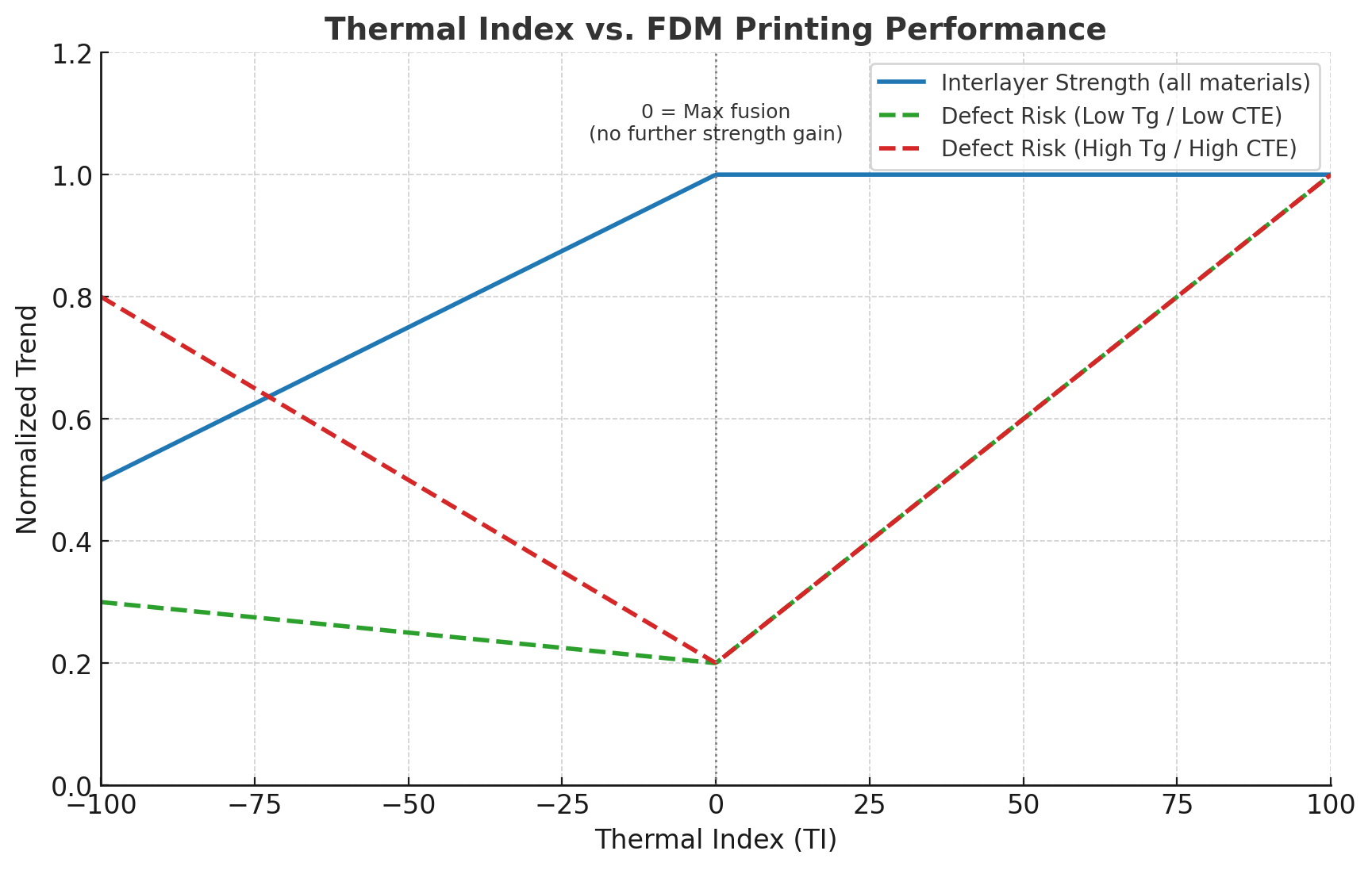
¶ Scale: -100 → 100
- TI = 0: Interlayer bonding reaches the maximum achievable limit.
- TI > 0: ⚠️ No further strength gain, but overheating/collapse risk rises.
- TI < 0: ❄️ Not necessarily failure — material-dependent behavior.
¶ Material Dependence
- Low Tg / Low CTE materials (e.g., PLA):
- Lower TI may reduce interlayer strength.
- Visible defects are minimal.
- High Tg / High CTE materials (e.g., PC, PA-CF):
- More prone to warping/cracking.
- Severity depends on geometry and first-layer adhesion:
- Stress concentrators → higher risk.
- Strong adhesion suppresses warping but not internal stress.
Note: Our simulation uses material-specific parameters beyond Tg for accuracy. Tg is an accessible way to explain why time above a threshold temperature drives bonding strength.
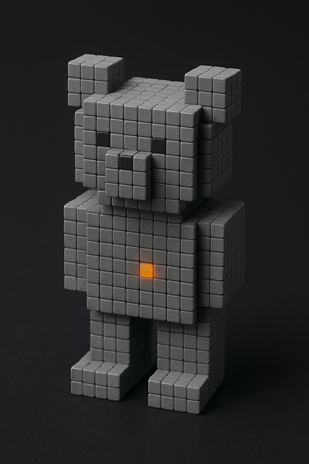 Representation of a voxel |
 A single voxels thermal history |
¶ 1) Nozzle Temperature
Cause: It’s intuitive to think “colder part → increase nozzle temperature.”
Effect: Once filament exits the nozzle (e.g., a 0.2 mm × 0.4 mm strand), it loses heat in milliseconds. That brief spike contributes little to thermal index. The main benefit of higher nozzle temp is improved melt flow (higher volumetric capacity/ability to get a higher flow rate), not keeping layers warm longer.
Action:
- Set nozzle temperature to the highest safe value (or profile recommendation).
- Use a temperature calibration tower to balance against stringing and artifacts.
ELI5: Pouring boiling water onto a thick cold plate warms it for only a moment; the plate doesn’t stay hot, so the “extra heat” barely counts.
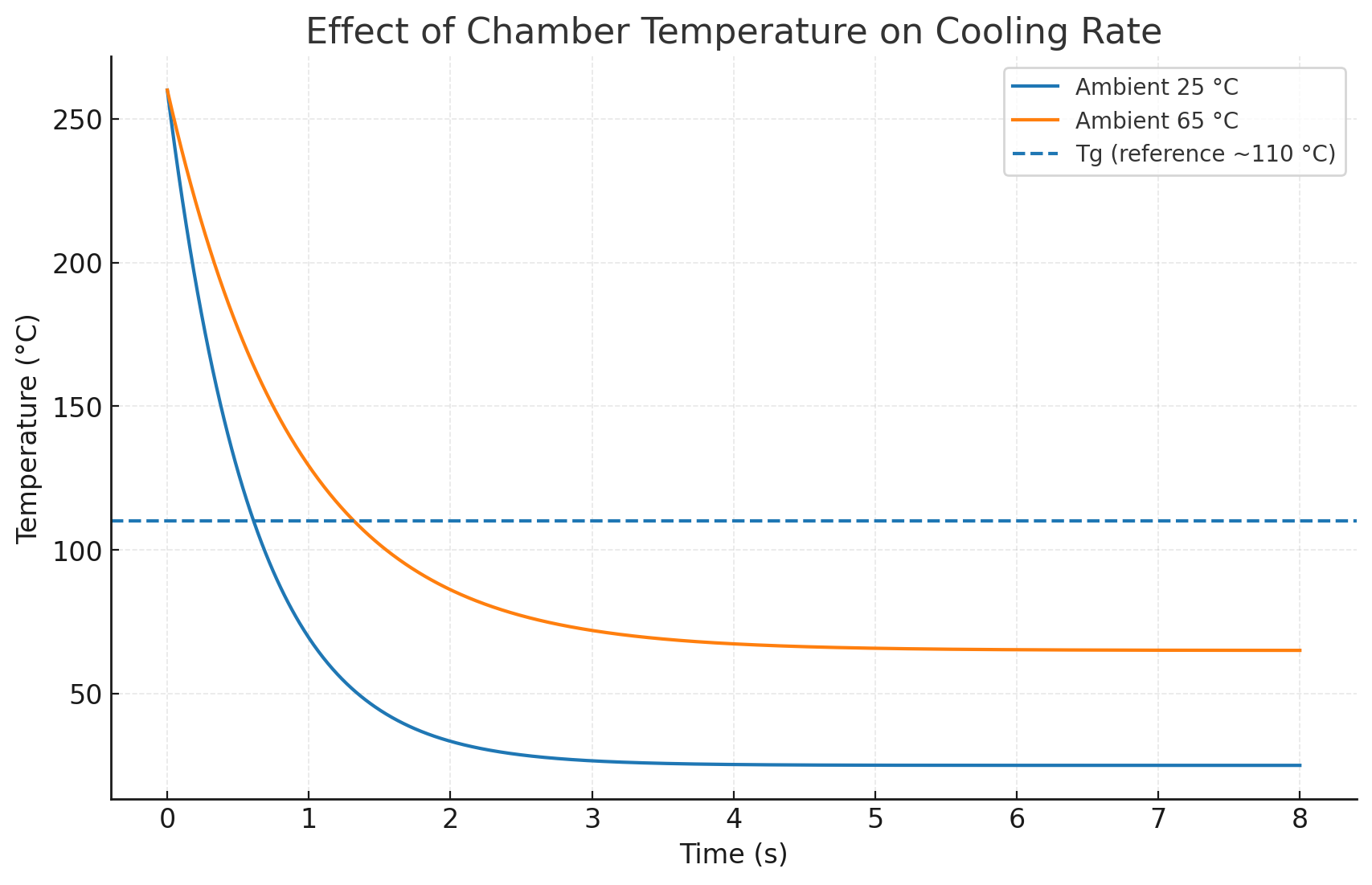
¶ 2) Chamber Temperature
Cause: The chamber sets the surrounding air temperature and therefore impact the cooling rate.
Effect: A warmer chamber reduces the temperature gradient, slowing cooling. This extends the time a voxel hangs near the welding range so the next layer’s reheating is more effective. However, typical chambers (≤ ~65 °C) are far below ABS/PC Tg (> ~100 °C), so benefits plateau.
Action:
- ABS/PC: Use the maximum safe chamber temperature (or profile recommendation).
- PLA/PETG: Avoid overheating; lower Tg means a warm chamber can cause softening/sag.
ELI5: Tea stays warm longer in a heated room, but the room won’t make it boil again.
¶ 3) Bed Temperature
The heated bed is not just for first-layer adhesion. It acts as a constant thermal reservoir that slows cooling in the lower layers and, in open printers, also helps warm the surrounding air (a poor man’s chamber heater).
- Raise bed temp as much as possible (within material guidelines) to boost the thermal index in lower layers.
- If no dedicated chamber heating exists, the bed will partly heat the print environment — making it especially critical for ABS, PC, PA, etc.
- But caution: bed temp should stay below the material’s Tg (or equivalent reference) to prevent base-layer sagging or collapse.
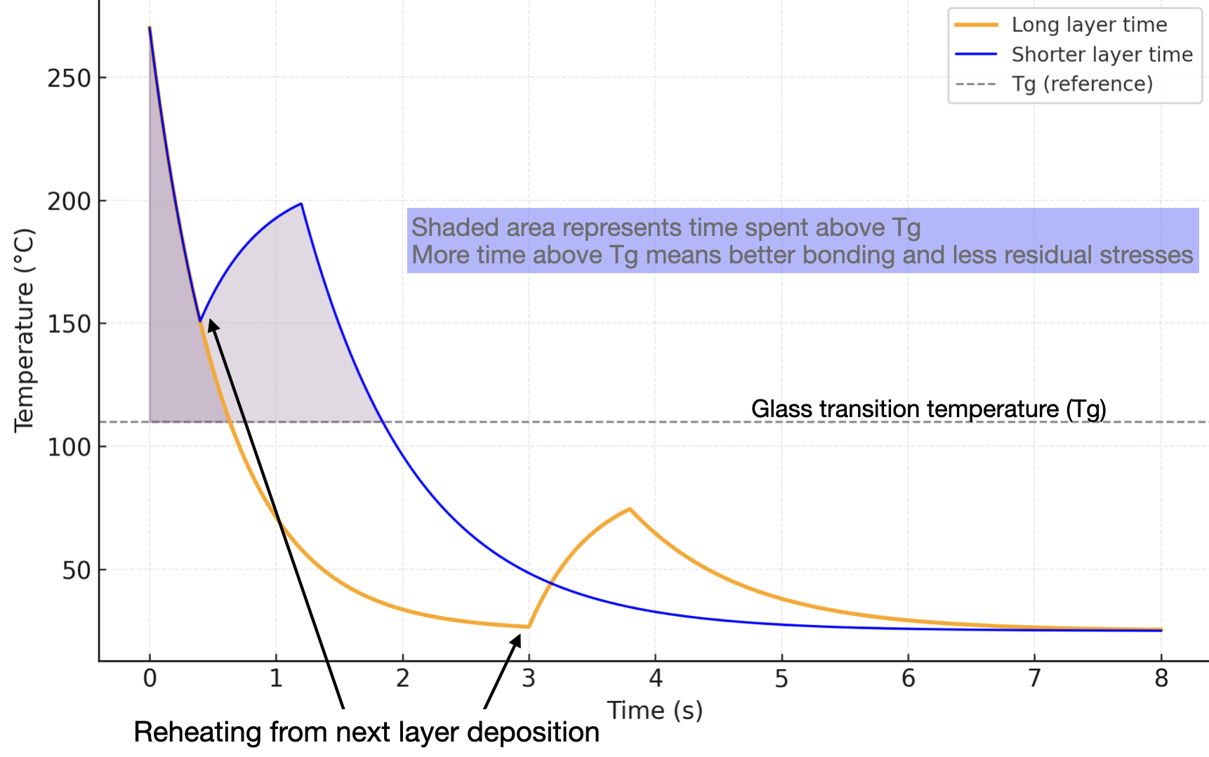
¶ 4) Layer Time (The Biggest Lever)
Cause: Thermal index is dominated by the inter-layer interval (“layer time”)—the delay between deposition and reheating by the next layer.
Effect:
- Short layer time → voxel hasn’t cooled much before reheating → warmer, stronger bonding.
- Long layer time → voxel cools well below Tg before reheating → colder, weaker bonding.
Action (to warm the part):
- Increase print speed (within your volumetric flow limit) to reduce layer time.
- In the Cooling tab, relax slow-down features that enforce a minimum layer time (reduce “Minimum layer time”, raise/disable “Slow down for cooling”).
- If speed is capped by flow rate (see §4), reduce layer length:
- Lower infill %
- Fewer wall loops/shells
- Smaller cross-section / scale down (if acceptable)
![Initial cooling is extremely fast]](/ti_vs_layer_time_clean_pretty.png)
¶ 5) Hardware Limits/Max Volumetric Flow (The Ultimate Limits)
Cause: Motion speed ≠ extrusion speed. The real ceiling is maximum volumetric flow rate (Q) in mm³/s.
Effect: Even if firmware says “500 mm/s”, if your nozzle/hotend can only melt & extrude Q_max, the slicer will slow down or you’ll under-extrude. Thermal index improvements are capped once Q_max is reached.
Action:
- Calibrate Q_max with a flow tower.
- Raise nozzle temperature (within safe limits) to increase melt flow.
- Accept this ceiling as beyond it, layer time cannot be reduced further by speed.
![Initial cooling is extremely fast]](/flow_vs_speed_saturating_dual_clean_title.png)
¶ 6) Fan Settings
Cause: Part cooling fans increase convective cooling.
Effect:
- ABS/PC (high Tg): Fans shorten the bonding window → parts read “colder”.
- PLA/PETG (low Tg): Fans prevent overheating/sagging → parts look better.
Action:
- ABS/PC: Lower or disable part cooling if the simulation shows “too cold.”
- PLA/PETG: Use the filament profile’s recommended fan settings.
- Do not adjust fan for overhangs or bridges from defaults or set these to requirements you know that work.
ELI5: Blowing on soup cools it faster - Good for when it’s too hot, bad for when you need it to stay warm.
¶ 7) Layer Height & Width
-
Thicker beads = slower cooling
A larger layer height or extrusion width means more plastic in each road. Bigger thermal mass cools more slowly, so the voxel stays above Tg longer → stronger bonding. -
Impact on thermal index
Increasing layer height or width can push thermal index closer to the target by extending the effective thermal history. This is especially relevant for large parts or when you’ve already maxed out speed and flow rate. -
Practical constraints
- Overhangs & bridges: Larger beads sag more, so increasing height/width makes unsupported features harder to print cleanly.
- Surface finish: Thicker layers = rougher vertical surface appearance.
- Compatibility: You can often apply bigger beads safely to infill first, then decide if it’s acceptable to expand to perimeters.
![Initial cooling is extremely fast]](/layer_height_width_cooling_clean_notitle.png)
¶ 8) Geometry Levers (When Speed Is Capped)
If you’ve hit the flow ceiling or motion constraints, the remaining lever is shortening layer length to reduce layer time.
Action (final resort, strategic):
- Lower infill % (e.g., 15 % → 5 %) if strength/top-surface support allows.
- Change infill type (e.g., lightning) if strength allows.
- Reduce wall loops/shells if mechanical/visual requirements permit.
- Scale down the part and assemble if functionality allows.
Trade-off: Lowering infill or walls can reduce layer time and enhance interlayer bonding through higher heat accumulation. However, this also decreases the overall structural strength of the FDM part. Therefore, these changes are only recommended when you fully understand the expected role of infill and shells in your design. Use cautiously.
¶ ✅ Summary
- Thermal index tracks time above a welding-useful range (we reference Tg to explain it).
- Nozzle temp: boosts flow capacity; minimal direct impact on warmth.
- Chamber temp: slows cooling but has a capped benefit.
- Bed temp: slows cooling in lower layers and passively warms chamber air; set high but below Tg.
- Layer time: shorter = warmer (biggest lever).
- Flow ceiling: defines the speed upper bound.
- Fans: help PLA/PETG; often hurt ABS/PC warmth (but needed for fine features e.g. on individual miniatures).
- Final resort: reduce infill, shells, or size when speed can’t increase.
For ABS/PC, warming up typically also reduces warping risk. For PLA/PETG, balance warmth against overheating.